 |
 |
 |
 |
 |
 |
 |
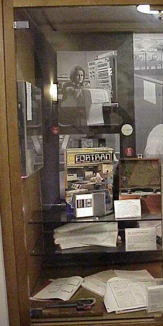
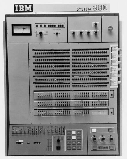
Original Display: IBM 360-40 [CHM]
 |
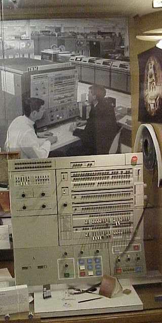
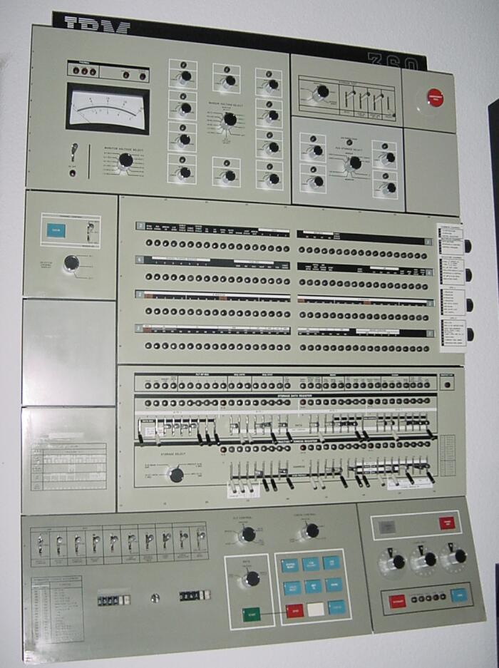
Main part of Current Display: FAA 360 - 9020 [Gio]
[New Beginnings Antiques (NBA), Gio, obtained August of 2003]
Central control panel for a Triplex IBM 9020E System (1971).
|
|
|
|
|
|
|
|
|
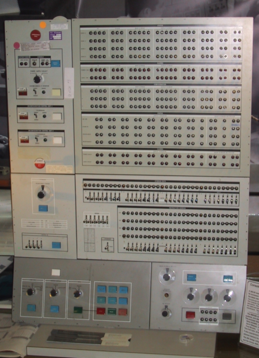
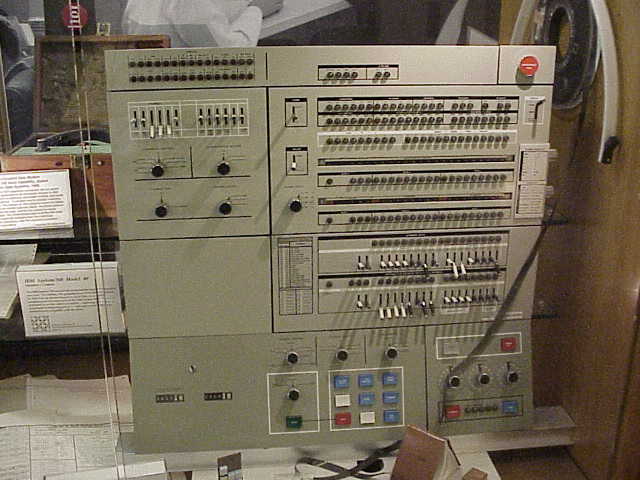
[New Beginnings Antiques (NBA), Gio, obtained August of 2003]
Central control panel for a Triplex IBM 9020E System (1971).
Using the 9020 control panel any of the actual processors' data
channels and control flows could be checked and, if needed, taken
off-line. Off-lined systems could then be further checked and repaired
using their own control panels, but the control system was unique.
The 9020 control system had a a 32-bit data path, 32 control switches,
and dials to select the computers and channels for display and
control, although the 360-65 computational units themselves had a
64-bit data path.
In extreme emergencies a red pull switch stopped
everything, requiring several engineers to spend many hours to check
and restore the systems.
Only 25 of these machines were built. The machine on display here was manufactured in 1971 and taken out of service in 1993. The main computing function of the FAA system was taken over by IBM System/370 model 3083 computers in 1986, but the 9020 continued to supply the display services. The life of the FAA 9020 system extended well beyond the life span of other IBM 360 systems, which were discontinued in 1977. The FAA system was hard to replace because of the complexity of the Flight Control Software, and many attempts failed to achieve adequate reliability [Gary Stix: "Aging Airways"; Scientific American, May 1994, pages 96-104].
Information about the IBM 9020 is at The Gallery of Old Iron. More photographs for this installation are at "Information about the FAA 360-9020E Triplex Computer".
The software for the FAA 9020 system was developed over three years starting in in 1965. It remained operational for 30 years. It consisted of over 2 million statements, mainly written in the JOVIAL language [Robert N. Britcher: The Limits of Software; Addison Wesley, 1999]. JOVIAL, Jules Schwartz' Own Version of the International Algebraic Language, was developed at System Development Corporation (SDC) based on IAL, a predecessor of Algol 60. SDC was later taken over by Burroughs, which after a merger with UNIVAC, became UNISYS Corporation.
The software is being rewritten in ADA, See FAA news of 9 October 2007.
On early computers program control was still partially under manual control. Much debugging could also take place. Programs could be stopped, execution could be stepped instruction by instruction, or program control be switched to other memory locations and restarted there. The contents of all registers, any memory cell, and the status of input-output channels could be displayed by the operator.
Click on images to see larger pictures.
 |
 >
> |
|

|
| [CHM] | [Courtesy of | John Falk] | [?] |
| IBM 360-40 Front Panel | IBM 360-50 Front Panel | IBM 360-65 Front Panel | IBM 360-67 Front Panel |
| An IBM 360-40 was used at Stanford Hospital for accounting starting about 1970. This panel was on display and returned to the CHM in July 2002. | An early 360-50 was used at SLAC. The ACME project at the Stanford Medical School used one from 1966 to 1973. | A 360-65 was used as the primary machine for academic and adminsistrative computing at the Stanford Computation Center, 1967-19xx. | An IBM-360-67 had been ordered for the TSS timesharing system, which never appeared. The 360-65 was a place holder. Did a 360-67 ever replace the -65 at the Stanford Computation Center? |
| A 16-bit data path and 16 settable address bits, so 2 x 16 switches. The base registers and index registers could be set at the top left. | A 32-bit data path, 32 switches. All 24 address bits could be set directly. | A 64-bit data path, 64 switches, plus 24 switches to set the memory address. | Identical to the model 65, except for some segment protection. A 64-bit data path, 64 switches. |
The IBM/360 architecture was intended to cover the range from modest to large systems, and data-processing as well as scientific computation. The principal designers were
Information on the chronology of successor and predessessor IBM mainframes and their relation to Stanford is being collected.
  |
 |
In 1964, IBM's Solid Logic Technology (SLT) made its first commecial
application in IBM's System 360/Model 40. SLT reflected IBM's
uncertainty about the new technology known as Integrated circuits (ICs),
yet it also demonstrates a need to move beyond the discrete transistor
technology. Each SLT module contains four or five glass-passivated
transistor chips and several resistors, all mounted on a ceramic
substrate. IBM made hundreds of millions of SLT modules over the lifespan
of this technology.
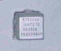
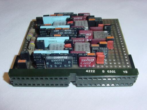
We display with the 9020 console a 1964 sample of a circuit card as used
in the 360 series and the 9020s.
It has 5 Solid Logic Technology (SLT) modules and a variety of discrete
components.
The SLT module on actual display has 5 transistors and two resistors;
Any capacitors needed had to be external.
The function of that SLT is likely a single (1-bit) flip-flop.
It was donated by [David Poppke, WA0VFY, Grand Forks, ND].
David also provided photographs documenting the
provenance of the 9020 panel
displayed.
The SLT shown in front of the 9020 panel is from the collecton of
The Computer History Museum, S175. CHM text transcribed by
Gio Wiederhold.
This web page also shows a plug-in card are 5 SLT modules and many
discrete components, as capacitors and large resistors.
The center image shows one SLT opened, so you can see the 3
transitors (shiny), three (dark) resistors and the connecting traces.
See also our Logic
Timeline in the basement.
 |
 |
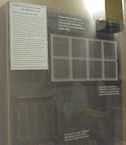 |
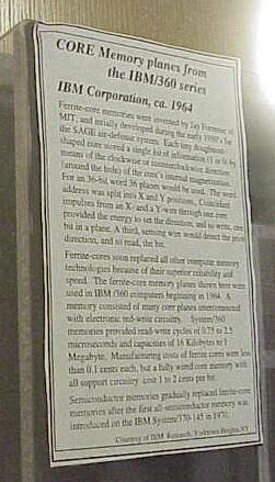
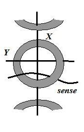
For a brief description of the technology look at the page on Core memory.
|
|
|
|
|
|